Raspberry Pi 4B LinuxCNC: Wiring and “Configuring” Eight NPN Normally Open Inductive Proximity Sensors to the Mesa 7I96S Card
This post describes how to wire eight NPN NO (Normally Open) inductive proximity sensors to the Mesa 7I96S card. The title and the wiring diagram refer to eight sensors, but I wired, configured, and tested only one. I originally bought eight sensors, but unfortunately managed to fry one, leaving seven available for future use. Again, this is not intended to be a tutorial, but rather a record of my learning progression.
🐧 Index of the Complete Series.
 |
|---|
| Raspberry Pi 4B LinuxCNC: Wiring and “Configuring” Eight NPN Normally Open Inductive Proximity Sensors to the Mesa 7I96S Card |
I am just an ordinary computer programmer and not trained in any of the electronic engineering disciplines. This LinuxCNC project is a learning process for me. This post is not meant to be a tutorial or instructional guide; it is my own documentation so I will not forget what I have learned.
I am not to be held responsible for any damages or injuries resulting from using the information presented in this post.
This post is a supplement to a 30-second YouTube video that was published on 5 March 2025:
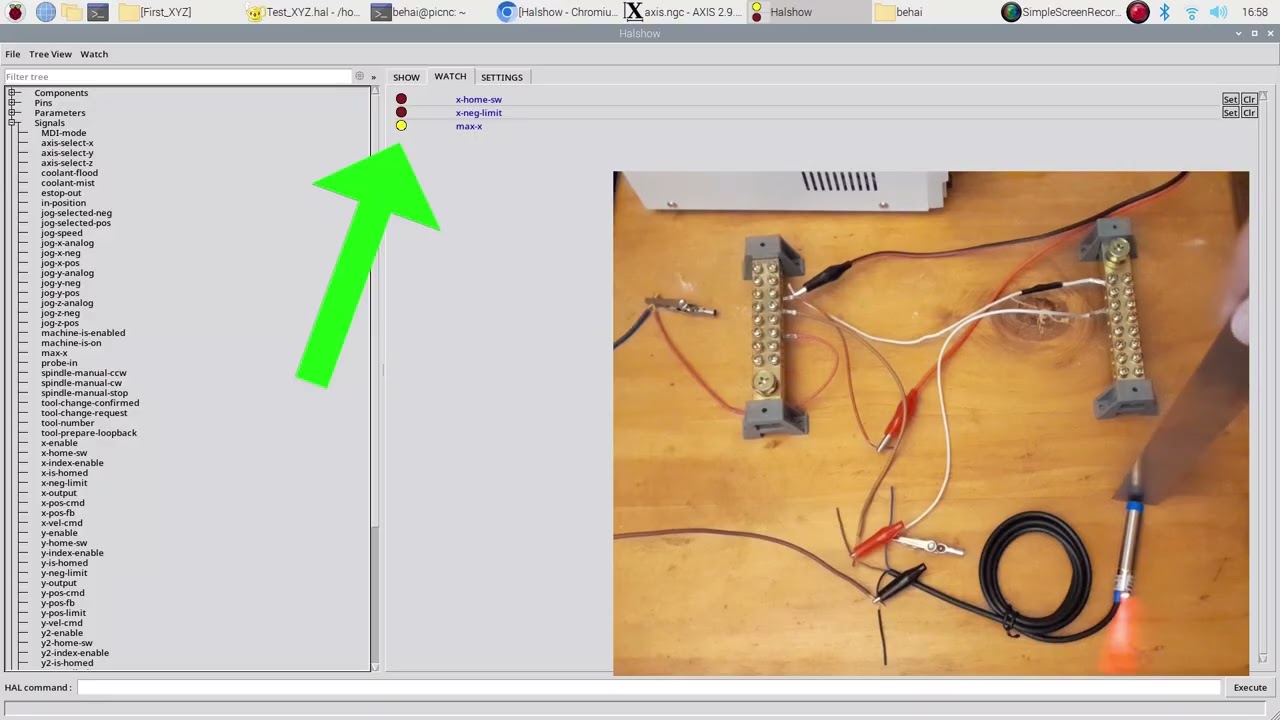
As I mentioned in a previous post, one of my objectives for this project is to document the various wiring configurations I have learned, so that if someone happens to be building a similar setup, it will hopefully give them a good head start. This post was written for completeness rather than to present anything new beyond the existing video.
❶ As with most other electronics topics, proximity switches were completely new to me. I spent a considerable amount of time researching the terminology and the different types of switches.
💡 First, the relevant documentation from the Mesa 7I96S Manual— page 14 states:
For PNP type sensors or switches with a common positive, the input common pin is grounded and the sensor or switch applies a positive voltage to the input pin to activate the input.
For NPN type sensors or switches with a common ground, the input common is connected to +5 to +36V and the input pins are grounded to activate an input.
The following are some of the YouTube videos I watched to learn about switches:
- 🎥 How to build a spaceship with a Mesa 7i76e ethernet card - a tutorial for new Linuxcnc users 37:20 -- PNP Proximity sensor
- 🎥 NPN Sensor Explained | Working, Wiring, and Testing
- 🎥 Inductive Sensors - PNP vs NPN - N.O. vs N.C. - Datalogic
- 🎥 NPN Inductive Proximity sensor. PNP Inductive proximity switch. PNP NPN proximity sensor Animation.
- 🎥 What is PNP Sensor? Working, Wiring and Testing
- 🎥 How to identify proximity switches NPN and PNP
- 🎥 3 Wire PNP & NPN Sensor wiring | Sensor Connection Diagram @TheElectricalGuy
- 🎥 Proximity Switch - Introduction, Wiring and Testing
- 🎥 Frankenlab CNC #13 - Sensors and Switches
The following are LinuxCNC forum discussions that I read while learning about the wiring:
- Mesa 7i96s limit switches and homing switches
- Mesa Cards and Inductive Proximity Switches
- 7i96S - NPN-NC Proximity Sensors and NPN-NO 3D Probe
- Home/Limit advice, please
- Help with Limits and Switch Configuration and Homing
- Homing with limit switches
🙏 I also have a friend who is a professional electronics engineer. He has patiently answered many of my questions and drawn numerous diagrams explaining the internal operation of various components, including the proximity switches. I am very grateful for his help.
Based on what I learned from the references listed above, together with the official LinuxCNC documentation Homing Configuration, I decided on the following approach for my machine:
- Two switches for each axis.
-
I plan to have four axes:
X,Y,Y-tandemandZ, which is why I bought eight switches. I am also aware that some machines successfully use only four switches.
❷ I began this work by asking for help in the following LinuxCNC forum discussion: Mesa 7I96S and Proximity Switches.
The diagram below is the one I submitted to the forum for approval:

The proposed wiring was approved by members of the Mesa support team on the
LinuxCNC forum. I then wired the first switch and configured it as the positive
limit switch for the X axis. I also documented the process in the
YouTube video mentioned earlier.
The diagram below shows my intended wiring for all eight switches:

💥 Please note that, although the diagram shows all eight switches, I have wired and tested only one. The components are currently laid out on a coffee table, so the wiring is a little untidy.
❸ As described in an earlier article, I am using the MEAN WELL MDR-100-24 PSU to power the proximity switches. This PSU also supplies power to the contactor coil. I have verified that it can provide sufficient current for both the contactor coil and the proximity switches.
❹ I sourced the switches and the mounting brackets from a local supplier. (I have no affiliation with the supplier.)
- LJ12 Angle Mounting Bracket
-
Inductive Proximity Sensor – LJ12A3-4-Z/BX
Specifications:
- Model: LJ12A3-4-Z/BX
- Output Type: NPN NO (Normally Open)
- Detecting Distance: 4mm±10%
- Theory: Inductive Sensor
- Wire Type: 3 Wire Type (Brown, Blue, Black)
- Switch Appearance Type: Block Type, Aluminum Shell (it is actually “cylindrical threaded inductive proximity sensor”.)
- Supply Voltage: DC 6-36V
- Current: 300mA
- Detect Object: Iron
- Diameter: 12mm
- Cable Length: 1M/3.3Ft
My temporary wiring works, but it is not intended to be the final installation. I understand I should use shielded wires such as this one to connect the switches to both the Mesa 7I96S and the 24 VDC power supply.
The three wires (brown, blue, and black) on the sensors are quite small and appear fragile. I have not yet worked out the best way to connect them to the shielded cable. This is something I still need to resolve before completing the final wiring.
❺ To get LinuxCNC to recognise the single wired switch, use the Mesa
Configuration Wizard,
PnCconf.
In the TB3 tab, select X Maximum Limit for the first
INM input entry. This switch is connected to the IN0
input on the TB3 isolated input terminal block, as
illustrated. This TB3 tab is shown
in the screenshot below:

I need to refresh my memory, but I believe the following entries are created in
the main
Test_XYZ/Test_XYZ.hal
file:
80
81
82
83
84
# ---setup home / limit switch signals---

net x-home-sw     =>  joint.0.home-sw-in
net x-neg-limit     =>  joint.0.neg-lim-sw-in
net x-pos-limit     =>  joint.0.pos-lim-sw-in
Every time we run
PnCconf and save the
configuration, manually added entries in the generated main .hal
file may be overwritten. They should not be relied upon for permanent custom
changes. Manually added HAL entries should be placed in the
custom.hal file.
❻ To test the switch, launch LinuxCNC, enable the machine, and move a metal object towards the blue sensing end of the switch. When it is close enough, the light on the switch will turn on.
❼ We can also monitor the internal HAL signals using the
halshow CLI.
💡 LinuxCNC must be running in order for halshow to access
internal Components, Pins, Parameters,
Signals, etc.
In a Terminal window, type halshow and press Enter.
A screen similar to the screenshot below will appear:

Locate max-x under Signals, as illustrated below:

Click max-x to add it to the WATCH list on the
right-hand side:

Move a metal object closer to the blue sensing end. When it is close enough,
the light on the switch will turn on, and the max-x entry in the
WATCH list will turn yellow, as illustrated in the screenshot below:

💥 This is as far as I have managed to understand the switches at this stage. I understand that I will need to do more study to get them working properly once I have a complete machine. The reason I am confident in the wiring of all eight switches is, as mentioned earlier, my initial diagram submitted to the LinuxCNC forum. That diagram specifies eight switches, and it was confirmed as correct by the Mesa support team on the LinuxCNC forum.
The remaining seven switches should follow the same wiring and configuration pattern; however, they will be fully verified once the machine is assembled.
❽ I hope this article contains some useful information. It is merely documentation of the work I have done, so that I can refer back to it whenever I need to refresh my memory.
Thank you for reading. I hope you find this record of my learning process helpful for your own setups. Take care and stay safe!
✿✿✿
Feature image source:
- https://www.instructables.com/Easy-Raspberry-Pi-Based-ScreensaverSlideshow-for-E/
- https://store.mesanet.com/index.php?route=product/product&product_id=374
- https://forum.linuxcnc.org/show-your-stuff/32672-linuxcnc-logo?start=20#gallery-6